Measuring the flow of liquids is a critical need in many industrial applications. In some operations, the ability to conduct accurate flow measurements is so important that it can make the difference between making a profit or taking a loss. In other cases, inaccurate flow measurements – or failure to take measurements – can cause serious (or even disastrous) results.
With most liquid flow measurement instruments, the flow rate is determined inferentially by measuring the liquid’s velocity or the change in kinetic energy. Velocity depends on the pressure differential that is forcing the liquid through a pipe or conduit. Because the pipe’s cross-sectional area is known and remains constant, the average velocity is an indication of the flow rate. The basic relationship for determining the liquid’s flow rate in such cases is:
Q = V x A
Where
Q = Liquid flow through the pipe
V = Average velocity of the flow
A = Cross-sectional area of the pipe
Other factors that affect liquid flow rate include the liquid’s viscosity and density, as well as the friction of the liquid in contact with the pipe.
What is a Flow Meter?
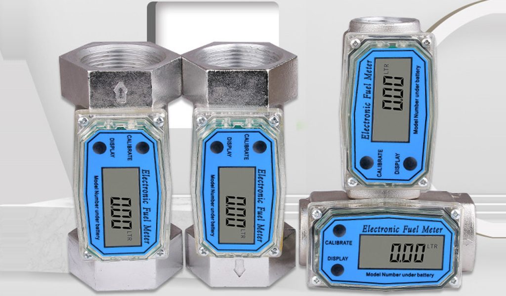
A flow meter (or a flow sensor) is an instrument that is used to indicate the amount of liquid, gas, or vapor moving through a pipe or conduit by measuring linear, non-linear, mass, or volumetric flow rates. Since flow control is often essential, measuring the flow of liquids and gasses is a critical need for many industrial applications – and there are many different types of flow meters that can be utilized depending on the nature of the application.
When choosing a flow meter, one should consider such intangible factors as familiarity of plant personnel, their experience with calibration and maintenance, spare parts availability, and meant time between failure history, etc., at the particular plant site. It is also recommended that the cost of the installation be computed only after taking these steps. One of the most common flow measurement mistakes is the reversal of this sequence: instead of selecting a sensor which will perform properly, an attempt is made to justify the use of a device because it is less expensive. Those “inexpensive” purchases can be the costliest installations.
How to Choose a Flow Meter
The basis of good flow meter selection is a clear understanding of the requirements of the particular application. Therefore, time should be invested in fully evaluating the nature of the process fluid and of the overall installation. The development of specifications that state the application requirements should be a systematic, step-by-step process.
Initial Steps
The first step in the flow sensor selection process is to determine if the flowrate information should be continuous or totalized, and whether this information is needed locally or remotely. If remotely, should the transmission be analog, digital, or shared? And, if shared, what is the required (minimum) data-update frequency? Once these questions are answered, an evaluation of the properties and flow characteristics of the process fluid, and of the piping that will accommodate the flow meter, should take place (Table 1).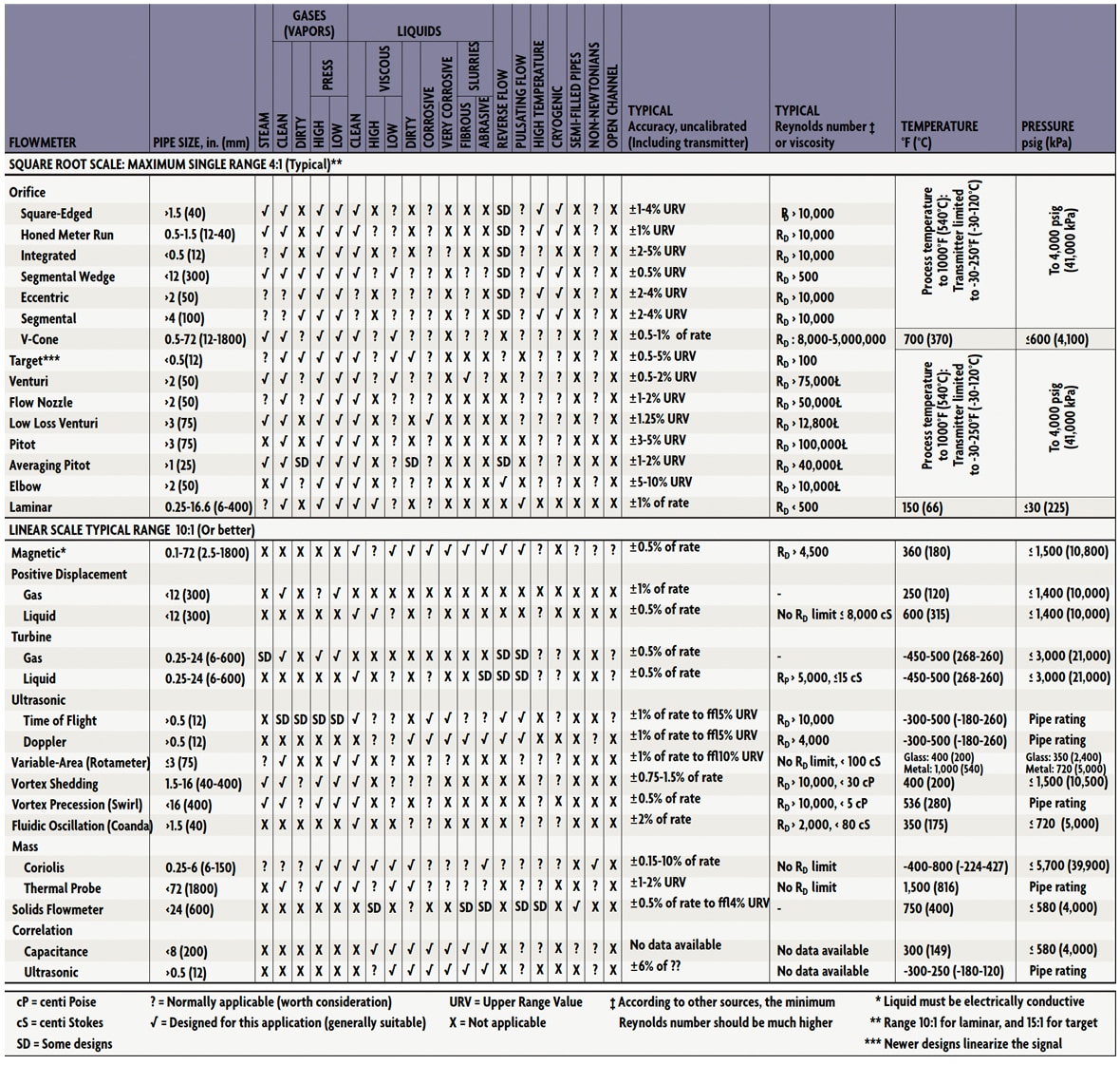 Table 1: Flow Meter Evaluation Table
Fluid and Flow Characteristics
The fluid and its pressure temperature, allowable pressure drop, density (or specific gravity), conductivity, viscosity (Newtonian or not?), and vapor pressure at maximum operating temperature are listed, together with an indication of how these properties might vary or interact. In addition, all safety or toxicity information should be provided, together with detailed data on the fluid’s composition, presence of bubbles, solids (abrasive or soft, size of particles, fibers), tendency to coat, and light transmission qualities (opaque, translucent, or transparent?).
Pressure and Temperature Ranges
Expected minimum and maximum pressure and temperature values should be given in addition to the normal operating values. Whether flow can reverse, whether it does not always fill the pipe, whether slug flow can develop (air-solids-liquid), whether aeration or pulsation is likely, whether sudden temperature changes can occur, or whether special precautions are needed during cleaning and maintenance, these facts, too, should be stated.
Piping and Installation Area
Concerning the piping and the area where the flow meter is to be located, the following information should be specified: For the piping, its direction (avoid downward flow in liquid applications), size, material, schedule, flange-pressure rating, accessibility, up or downstream turns, valves, regulators, and available straight-pipe run lengths.
In connection with the area, the specifying engineer must know if vibration or magnetic fields are present or possible, if electric or pneumatic power is available, if the area is classified for explosion hazards, or if there are other special requirements such as compliance with sanitary or clean-in-place (CIP) regulations.
Flow Rates and Accuracy
The next step is to determine the required meter range by identifying minimum and maximum flows (mass or volumetric) that will be measured. After that, the required flow measurement accuracy is determined. Typically, accuracy is specified in percentage of actual reading (AR), in percentage of calibrated span (CS), or in percentage of full scale (FS) units. The accuracy requirements should be separately stated at minimum, normal, and maximum flowrates. Unless you know these requirements, your meter’s performance may not be acceptable over its full range.
Accuracy vs Repeatability
In applications where products are sold or purchased on the basis of a meter reading, absolute accuracy is critical. In other applications, repeatability may be more important than absolute accuracy. Therefore, it is advisable to establish separately the accuracy and repeatability requirements of each application and to state both in the specifications.
When a flow meter’s accuracy is state in % CS or % FS units, its absolute error will rise as the measured flow rate drops. If meter error is stated in % AR, the error in absolute terms stays the same at high or low flows. Because full scale (FS) is always a larger quantity than the calibrated span (CS), a sensor with a % FS performance will always have a larger error than one with the same % CS specification. Therefore, in order to compare all bids fairly, it is advisable to convert all quoted error statements into the same % AR units.
It is also recommended that the user compare installations on the basis of the total error of the loop. For example, the inaccuracy of an orifice plate is stated in % AR, while the error of the associated d/p cell is in % CS or % FS. Similarly, the inaccuracy of a Coriolis meter is the sum of two errors, one given in % AR, the other as a % FS value. Total inaccuracy is calculated by taking the root of the sum of the squares of the component inaccuracies at the desired flow rates.
In well-prepared flow meter specifications, all accuracy statements are converted into uniform % AR units and these % AR requirements are specified separately for minimum, normal, and maximum flows. All flow meter specifications and bids should clearly state both the accuracy and the repeatability of the meter at minimum, normal, and maximum flows.
Table 1 provides data on the range of Reynolds numbers (Re or RD) within which the various flow meter designs can operate. In selecting the right flow meter, one of the first steps is to determine both the minimum and the maximum Reynolds numbers for the application. Maximum RD is obtained by making the calculation when flow and density are at their maximum and viscosity at its minimum. Conversely, the minimum RD is obtained by using minimum flow and density and maximum viscosity.
If acceptable meeting performance can be obtained from two different flow meter categories and one has no moving parts, select the one without moving parts. Moving parts are a potential source of problems, not only for the obvious reasons of wear, lubrication, and sensitivity to coating, but also because moving parts require clearance spaces that sometimes introduce “slippage” into the flow being measured. Even with well-maintained and calibrated meters, this unmeasured flow varies with changes in fluid viscosity and temperature. Changes in temperature also change the internal dimensions of the meter and require compensation.
Furthermore, if one can obtain the same performance from both a full flow meter and a point sensor, it is generally advisable to use the flow meter. Because the point sensors do not look at the full flow, they read accurately only if they are inserted to a depth where the flow velocity is the average of the velocity profile across the pipe. Even if this point is carefully determined at the time of calibration, it is not likely to remain unaltered, since velocity profiles change with flowrate, viscosity, temperature, and other factors.
If all other considerations are the same, but one design offers less pressure loss, it is advisable to select that design. Part of the reason is that the pressure loss will have to be paid for in higher pump or compressor operating costs over the life of the plant. Another reason is that a pressure drop is caused by any restriction in the flow path, and wherever a pipe is restricted becomes a potential site for material build-up, plugging, or cavitation.
Mass or Volumetric Units
Before specifying a flow meter, it is also advisable to determine whether the flow information will be more useful if presented in mass or volumetric units. When measuring the flow of compressible materials, volumetric flow is not very meaningful unless density (and sometimes also viscosity) is constant. When the velocity (volumetric flow) of incompressible liquids is measured, the presence of suspended bubbles will cause error, therefore, air and gas must be removed before the fluid reaches the meter. In other velocity sensors, pipe liners can cause problems (ultrasonic), or the meter may stop functioning if the Reynolds number is too low (in vortex shedding meters RD > 20,000 is required).
In view of these considerations, mass flow meters, which are insensitive to density, pressure, and viscosity variations and are not affected by changes in the Reynolds number, should be kept in mind. Also underutilized in the chemical industry are the various flumes that can measure flow in partially full pipes and can pass large floating or settleable solids.
Maintaining a Flow Meter
A number of factors influence maintenance requirements and the life expectancy of flow meters. The major factor, of course, is matching the right instrument to the particular application. Poorly selected devices invariably will cause problems at an early date. Flow meters with no moving parts usually will require less attention than units with moving parts. But all flow meters eventually require some maintenance.
Primary elements in differential pressure flowmeters require extensive piping, valves, and fittings when they are connected to their secondary elements, so maintenance may be a recurring effort in such installations. Impulse lines can plug or corrode and must be cleaned or replaced. And improper location of the secondary element can result in measurement errors. Relocating the element can be expensive.
Flowmeters with moving parts require periodic internal inspection, especially if the liquid being metered is dirty or viscous. Installing filters ahead of such units will help minimize fouling and wear. Obstruction-less instruments, such as ultrasonic or electromagnetic meters, may develop problems with their secondary element’s electronic components. Pressure sensors associated with secondary elements should be periodically removed and inspected.
Applications where coatings may occur are also potential problems for obstruction-less instruments such as magnetic or ultrasonic units. If the coating is insulating, the operation of magnetic flowmeters will ultimately be impaired if the electrodes are insulated from the liquid. This condition will be prevented by periodic cleaning. With ultrasonic flowmeters, refraction angles may change, and the sonic energy absorbed by the coating will cause the meter to become inoperative.